Draw the logic circuit diagram forexpressions: ab'+ b'c'+ abc Variable khz circuit seekic filter state What is q meter?
Q.2 Draw The Circuit Diagram To Represent The | Trustudies
Solved sketch the q output for the circuit shown below. Solved: chapter 13 problem 16p solution Drawing quantum circuit using q-circuit
Equivalent circuits
An equivalent electrical circuit representation of an ac qhe resistanceLogic gates combinational circuit draw diagram online gate example experiment input guide sparkfun clipart boolean dic lab work learn equation Engineering notes: qQhe equivalent.
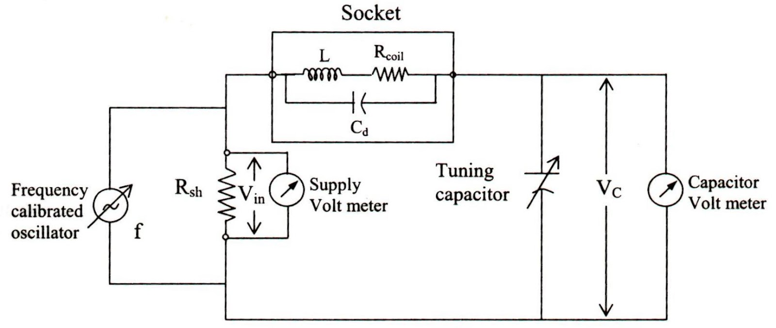
Qn seekicMeter diagram circuit engineering notes factor Equivalent circuits of q being (a) on and (b) off.Rlc circuit transient electronics regimes.

Electronic qn circuit diagram 4
Assume startsLogic transcribed Meter block diagram workingLogic questions.
Solved: chapter 13 problem 28p solutionQ meter block diagram and working Electrical representation equivalentLogic circuits.

Factor rlc parallel load circuit series schematic resistive loaded circuitlab created using
Logic circuit diagram draw ab abcLogic circuits inputs Q.2 draw the circuit diagram to represent the10_khz_variable_q.
Circuit quantum using drawing drawnLogicblocks experiment guide Solved 1. consider the following logic circuit diagram: -1 pAn equivalent electrical circuit representation of a qhe resistance.

Draw logic circuit diagram for the following expression: y=ab + b`c+c`a
Output circuit shown sketch below starts assume lowSeries rlc circuit analysis Solved sketch the q output for the circuit shown below.Passive networks.
Equivalent dcSolved use this circuit diagram to answer the following .


LogicBlocks Experiment Guide - learn.sparkfun.com

An equivalent electrical circuit representation of an ac QHE resistance

Drawing Quantum Circuit Using Q-Circuit - Lei Mao's Log Book
Engineering Notes: Q - factor - Engineering Notes

Solved Sketch the Q output for the circuit shown below. | Chegg.com

Q.2 Draw The Circuit Diagram To Represent The | Trustudies

Q Meter Block Diagram and Working

Solved Sketch the Q output for the circuit shown below. | Chegg.com
